


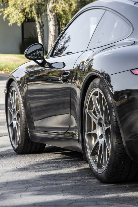
Sleek and agile, the new 991 Carrera is an impressive machine. Handling, power and styling make this a fun road car. Capable as it is, the balance between comfort and performance will leave some asking for a more visceral experience. Performance enthusiasts will desire more; more road feel, more grip, more control, more precision.
The GT3 is Porsche’s answer. It is the bridge between a standard Carrera and the Cup racecars. Equally at home on the track or performance street driving, the GT3 delivers a more raw experience with a suspension that is substantially firmer. Harder spring rates and bushings provide sharper, crisper suspension and steering feedback; something that we find slightly lacking on the standard Carrera. But with its raised element rear wing, no manual transaxle, no sunroof, reduced sound deadening, and other track-oriented compromises, the GT3 isn’t for everybody.
So what if you want your 991 Carrera to rival 991 GT3 handling without all the other GT3 baggage?
Perhaps you want GT3 handling AND the manual transaxle that Porsche won’t give you. Or maybe you want the handling without the big wing perched out back beckoning attention like some bejeweled codpiece. Or could it be you love your 991, but just want more performance that the standard 991 delivers.
Make it a car that performs great at the track on the weekend, and slips discreetly into the parking lot at work Monday morning. A true driver’s car with the appearance and features of the 991.
We thought this was a good idea, so we created the 991 Street/Track program.
Objective
Our objective is to build a package to take this production 991 and ‘un-compromise’ the suspension performance. We will add functionality that makes the GT3 work so well.
Specifically the 991 Street/Track Program will deliver the following to the 991 Carrera:
- Lower stance to match the GT3 ride height
- Introduce ride height & corner balance adjustability
- Spring rate options
- Retain PASM functionality
- Enhance precision and driver feedback
Parts List
There are fundamental differences between the 991 Carrera and GT3 suspensions that prevent simply retrofitting most 991 GT3 parts to the Carrera. So to achieve our program objectives , we’ve developed a slew of products for the 991 Carrera that will get us there.
Here’s a list of parts used in this 991 Street/Track program:
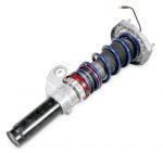 Front Coilover Sleeve Conversion Kit
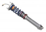 Rear Coilover Sleeve Conversion Kit
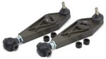 Adjustable Front Lower Control Arms
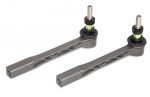 Bump Steer Adjustable Front Tie Rod Ends
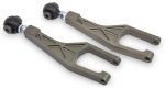 Adjustable Rear Lower Control Arms
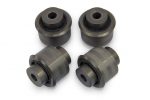 Lower Control Arm (Rear) Concentric Monoballs
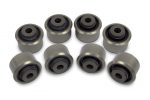 Upper Control Arms (Rear) Concentric Monoballs
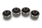 Track Rod (Rear) Concentric Monoballs
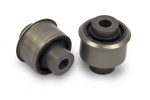 Wheel Carrier (Rear) Concentric Monoballs
Our sleeve conversion kit allows us to convert regular PASM or non-PASM shocks into fully functional height adjustable coilovers. With this kit we can install firmer springs, lower the car to the GT3 height and corner balance it, while retaining the PASM functionality.
Our adjustable lower control arms and wishbones provide extended range of camber and caster adjustment, while providing smooth, low-friction and non-deflecting control arm action.
The Monoballs replace rubber bushings in all other locations. Rubber compresses and deforms under stress causing the alignment to wonder unpredictably, causing precision and feedback to suffer.
For spring rates we opted to use 300in/lbs front and 550in/lbs rear. This is about 20% and 25% stiffer than the stock springs and will make a noticeable difference in performance and driver control – without being to harsh for street use. Other spring choices can be used.
Results

So what are the results? Stellar! The driver feels more connected to the road with more feedback and control. Noticeably firmer than stock, the car is in no way harsh. The spherical bearings deliver a comfortable ride and make no noise. There is slightly more audible road noise coupled into the chassis, but still the cabins is quieter than the GT3
The spring rates we chose worked well with the existing PASM system. 20% stiffer in front and 25% stiffer in rear was a good balance for sporting street use. For a more track oriented setup we would go a bit stiffer.
How did the suspension upgrades affect the car’s performance? Let’s hear it from the car owner himself:
“Drumroll… you nailed it. Perfect outcome. It’s exactly what you set out for. More engaging but not harsh. Better handling but still street worthy. I didn’t have any issues with driveways at all. I believe the car is ‘better’ and more sports purpose without the full gt3 treatment.”
The car feels much more like the GT3. Exactly what we set out to accomplish.


Tutorial Overview
While installing all these parts may sound daunting, it really isn’t. Luckily, the suspension of the 991 Carrera is surprisingly simple to work on. We’ve created the following tutorial to demonstrate exactly how we’ve overhauled the suspension. This tutorial covers complete suspension overhaul Including replacing suspension bushings and full coilover conversion.
We do recommend you have access to a shop manual and use all factory specified torque settings when re-installing fasteners.
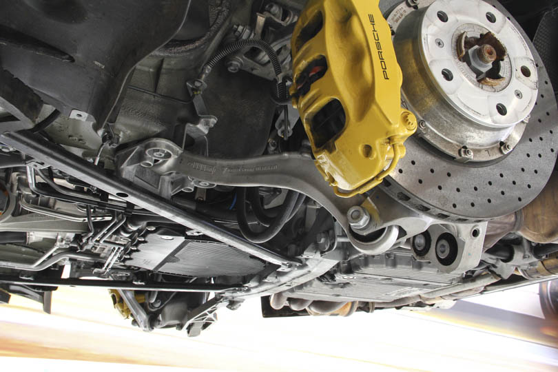
Begin by raising the car and removing the wheels. While a lift certainly makes this project easier, the entire project is readily doable using a jack and jackstands. Regardless of how you raise the car, be sure to use proper safety techniques. Never go under a car that is not safely supported.
Remove the front and rear underbody covers. These are secured with a series of threaded fasteners. Once the fasteners are removed the covers simply pull off the car.
Rear Suspension Tutorials
Strut Removal
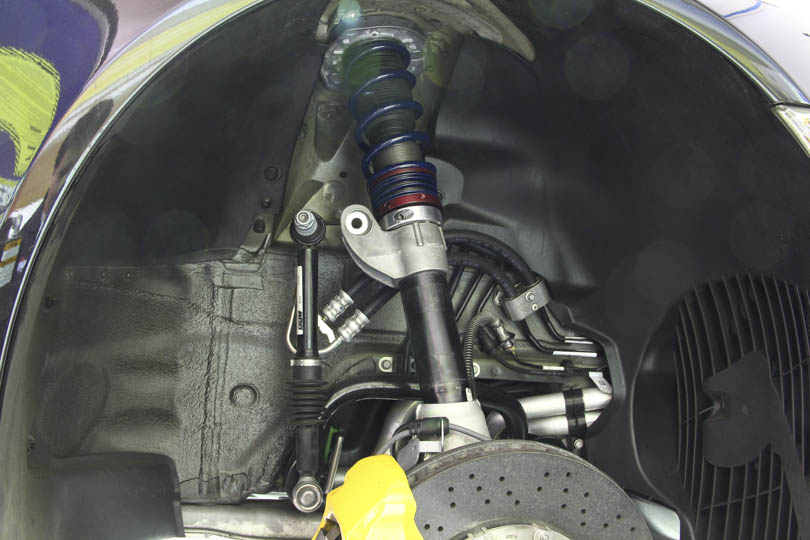
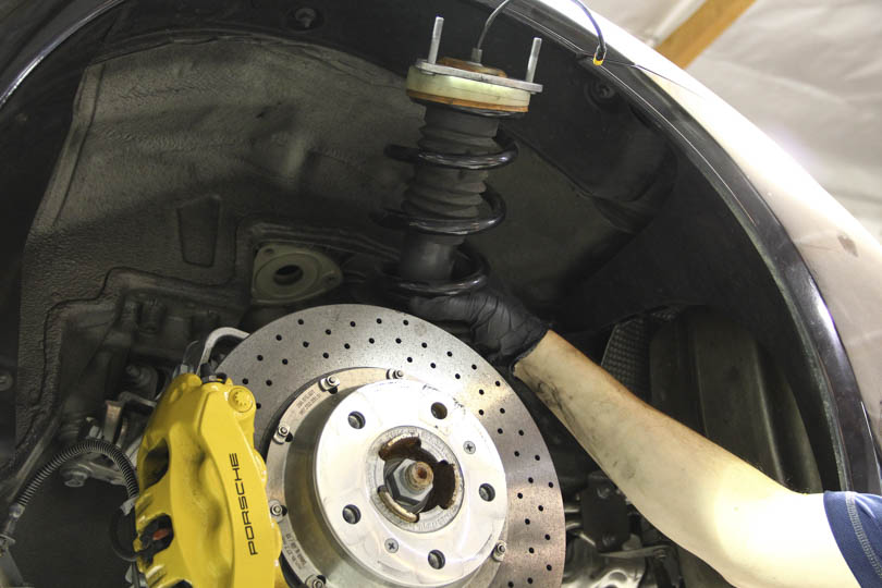
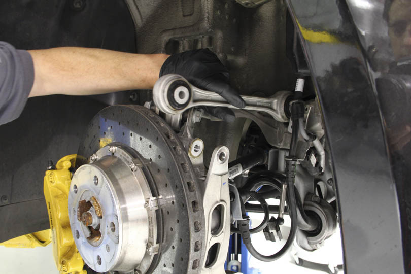
Let’s remove the front strut.
First, support the lower control arm on a stand, once the strut or the camber plate is disconnected, the lower assembly will want to droop down and possibly pinching or kinking hydraulic lines.
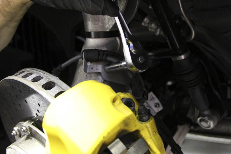
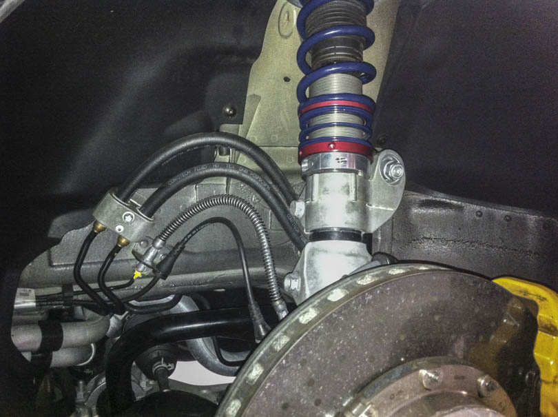
Disconnect the brake line support bracket to prevent the line from getting kinked.
Using an 18mm socket, disconnect the PDCC drop link if the car is equipped with one.
Using and 18mm socket, loosen up the bolt that clamps the strut to the wheel carrier. If the car is not equipped with PDCC, this bolt also holds the drop link.

Disconnect the PASM cable if your car is equipped with PASM shocks.
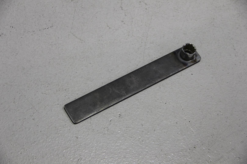
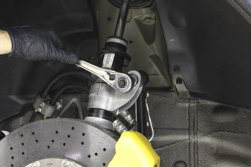
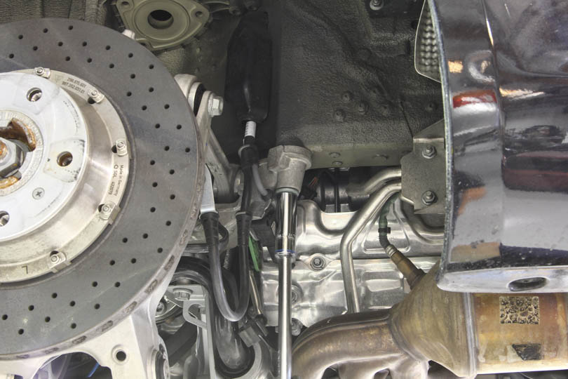
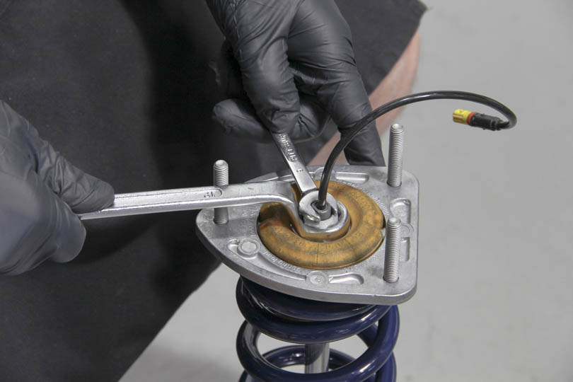
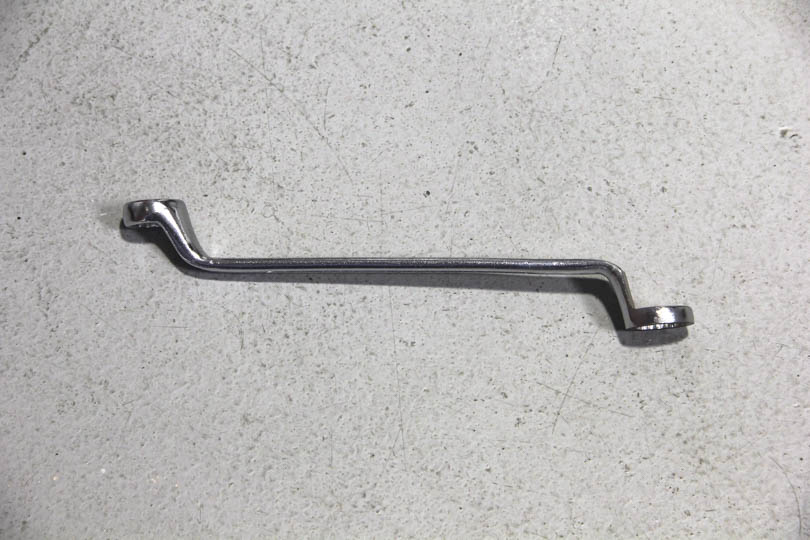
To disconnect the strut from the camber plate a special tool needs to be purchased or fabricated.
We’ve made the tool by using a flat bar with a hole drilled and a 21mm socket welded on.
The shock rod has to be held in place with a dog-leg 10mm wrench in order to rotate the 21mm nut. The PASM cable prevents the use of a regular socket.
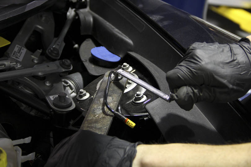
With the rod disconnected from the camber plate, carefully lower the assembly or raise the car to separate the strut from the camber plate. Be very careful not to lower the assembly too much and put excessive pressure on any of the lines.
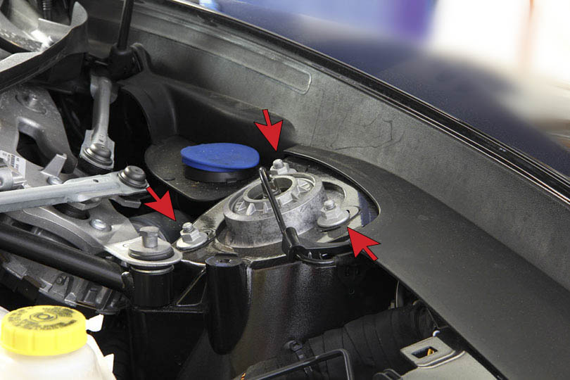
Removing the camber plate will make the extraction of strut and springs much easier but it will affect the camber settings and a re-alignment will be required. The camber plate is held in with three nuts. To remove the camber plate, use a 13mm socket to remove the 3 nuts.
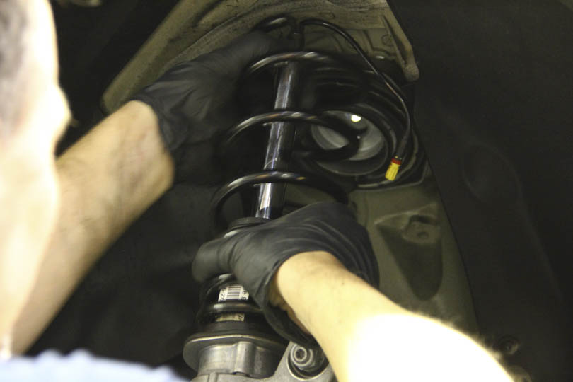
With the camber plate removed, the spring and strut insert can easily be removed by passing up through the camber plate hole in the chassis.
If you wish to retain the camber settings, it is possible to keep the camber plate in place, and use a spring compressor to get the spring and strut out.
However, removing the camber plate makes this process much easier. The opening is large enough to thread the spring straight out and pull the strut out without compressing the rod.
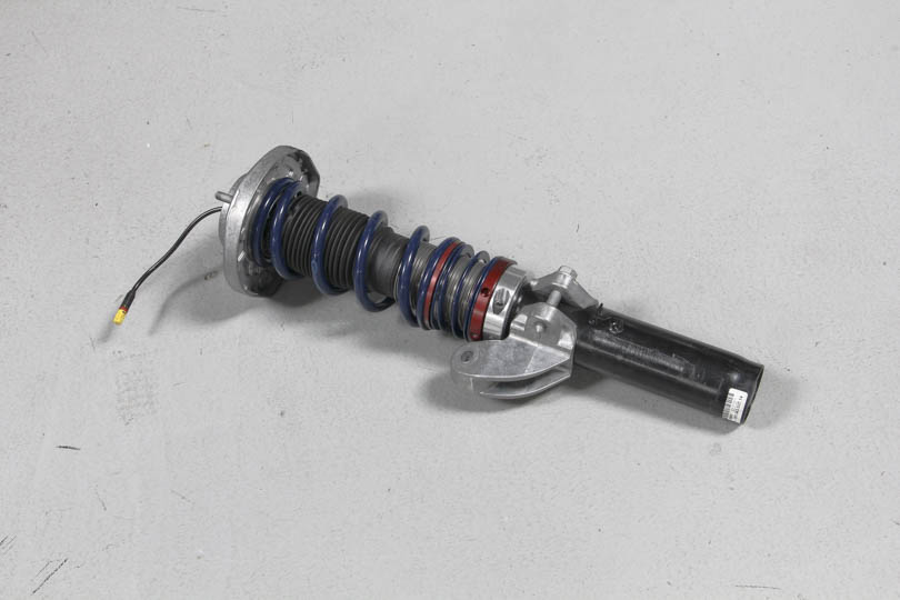
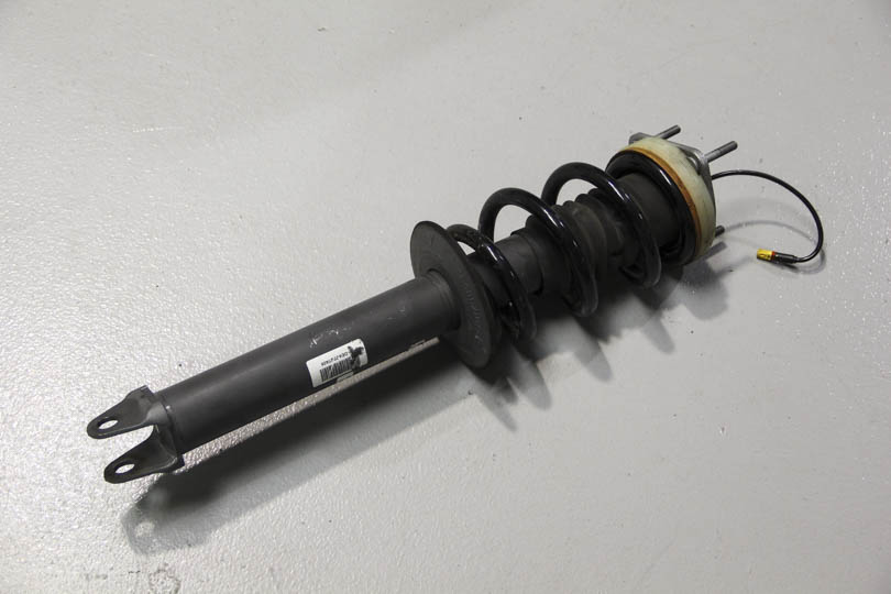
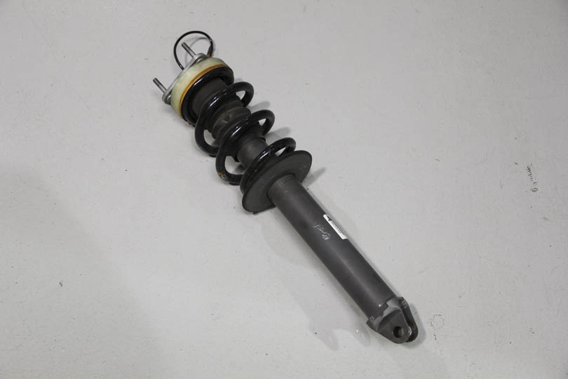
The strut is out and we can move on to the coilover conversion.
Strut Coilover Conversion
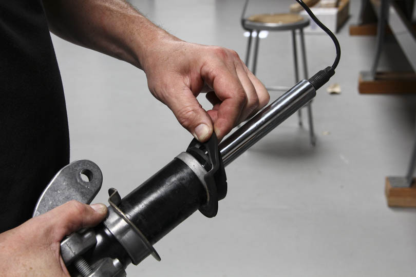
Remove rubber seal from around the strut.
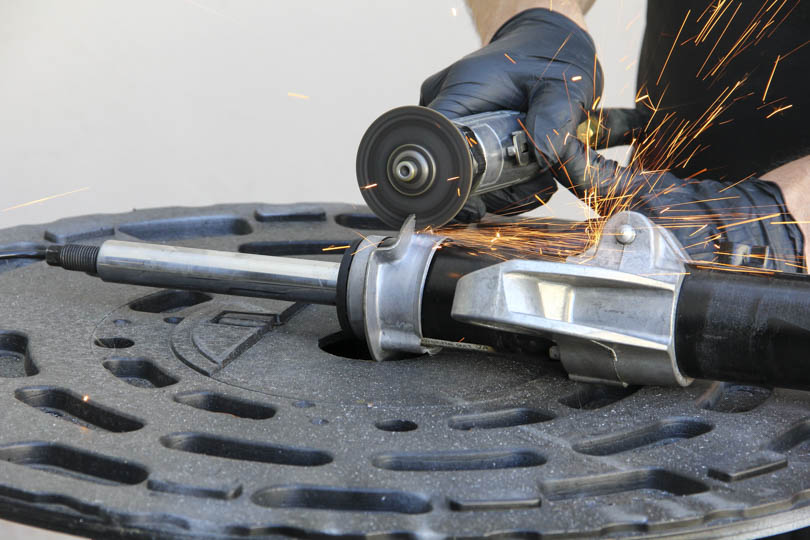
With a cutting wheel cut off the lower perch.
Make one complete cut on the ridge of the perch.
And make another partial cut to weaken the perch and use it as a hinge to bend the perch off.
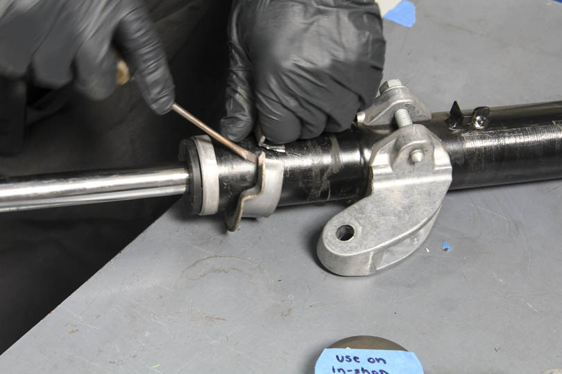
Using a screw driver, pray the perch apart and remove.
Next, put the sleeve base on by clamping it right above the drop link bracket.
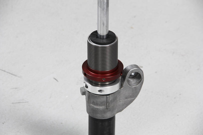
Pull the sleeve on and thread the lower perch on.
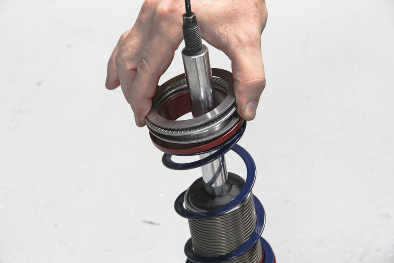
Insert the helper spring and the spring divider. On top of the spring divider, place the seat bearing sandwiched between two bearing thrust washers.
Inset the main spring, bump stop and the camber plate. If you wish to retain the OEM boot, it will fit inside the spring as well.
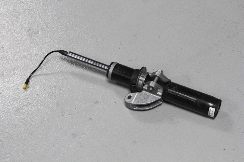
The strut is ready for installation.
Strut Installation
The strut is ready for installation.
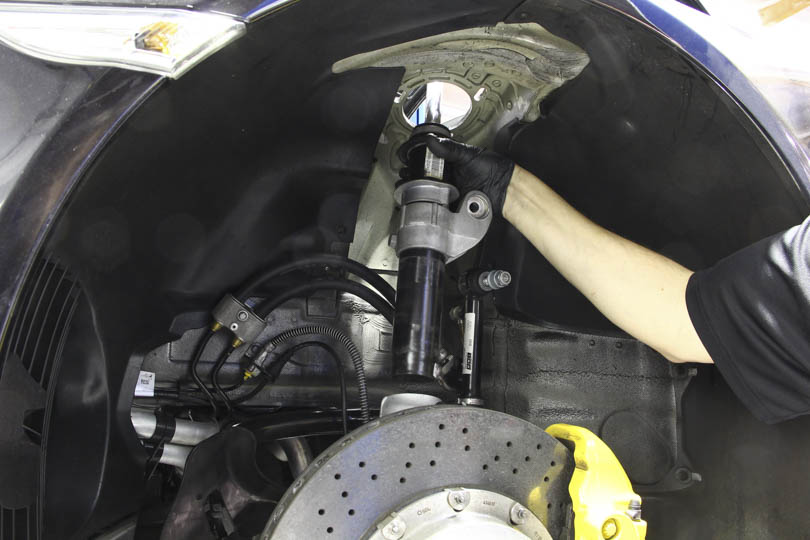
Bring down the upright assembly. Be careful not to stress or pinch any lines. Insert the bottom of the strut into the upright, and bolt the top camber plate in place.
Raise the upright until the strut seats itself. There should be only about 8mm space between upright and the PASM drop link bracket if so equipped.
Bolt back the strut clamp and the drop link and torque back the strut to camber plate bolt.
Control Arm Replacement
Now that the front upright is being supported by the strut we can remove the lower control arm.
Take off shield by prying off two tabs on the other side with a flat head screw driver. Pull to the side so it’s out of the way.
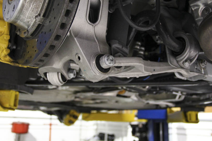
Detach front lower control arm. Caster arm to control arm bolt. Both nuts are 21mm.
Once out. Pull the caster arm out if the way.
Detach height sensor from control arm.
Loosen the nut with an 18mm socket. Remove the nut.
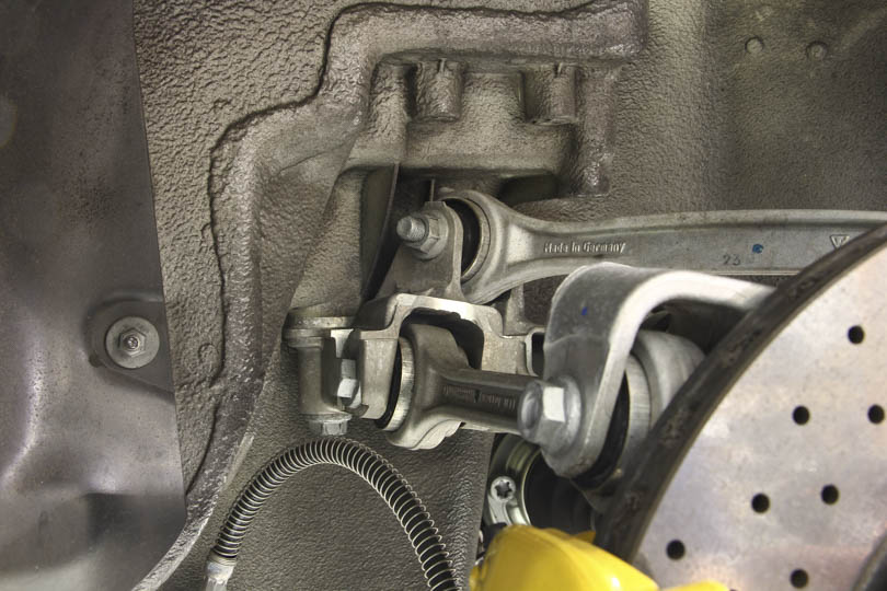
Disconnect inner bolt and let the control arm hang loose. This will give enough clearance for the ball joint separator.
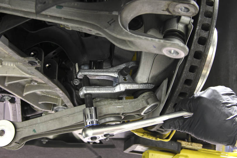
Use a ball joint separator tool, separate the ballpoint from upright and remove the control arm.
The arm should pop out with ease.
Reinstall the new control arm in reverse order. However instead of using the spreader, simply torque the ball joint nut and the control arm will seat itself properly.
Insert center bushing spacers and bolt down the caster arm.
Make sure that all bolts are torqued down.
Rear Suspension Tutorials
Shock Removal
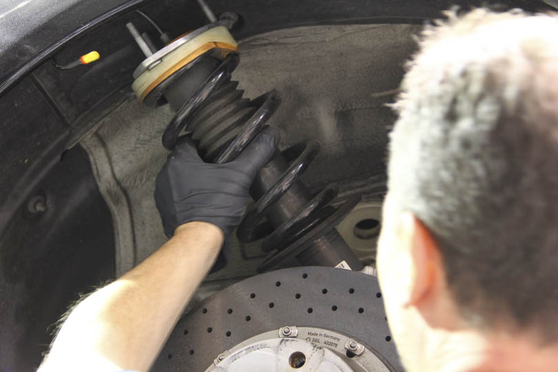
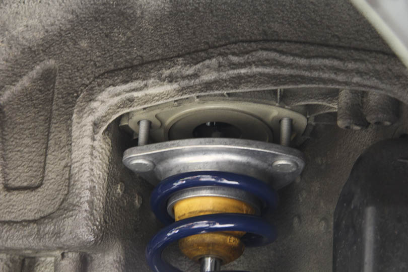
Start by unbolting the rear shock mounts. The top of the rear shocks is accessed through the rear seat area. To gain access, fold the rear seat backs down and pull up the carpet that lays vertically behind the seat backs. You have to give the carpet a good tug to get it out, but don’t worry. There is no glue or fasteners holding the carpet in, it just pulls up.
With the carpet out of the way you will see a large Styrofoam filler piece. Remove this piece and you will see the top of the rear shocks.
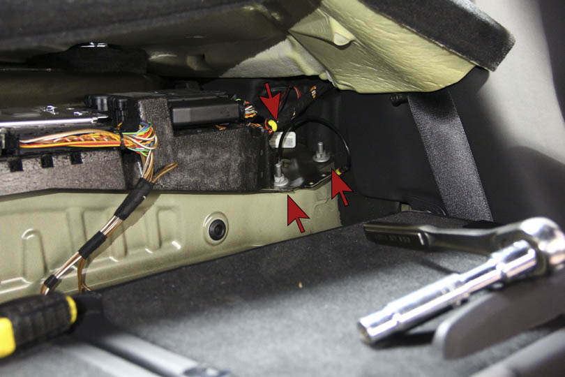
Disconnect the PASM cable if the car is equipped with PASM shocks. The shock mount is held in by three nuts. Remove the three nuts with a 13mm socket wrench.
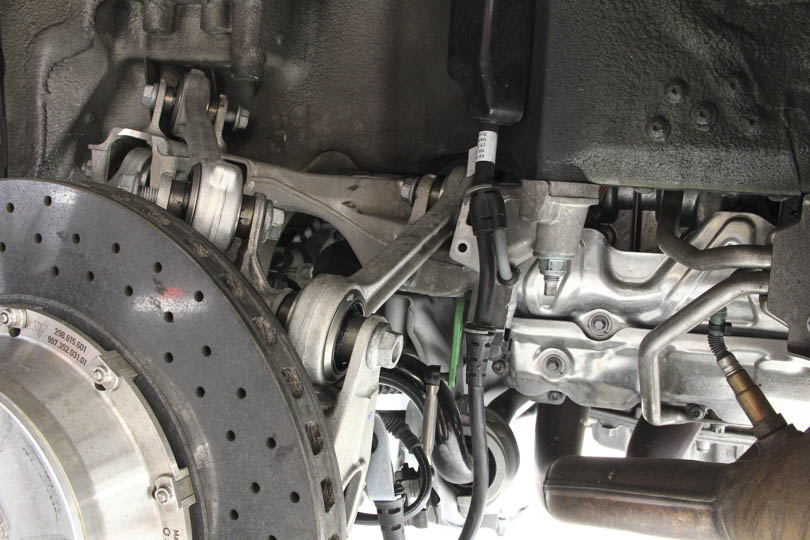
In order to gain access to the lower shock mount, the lower control arm needs to be disconnected.
To disconnect the lower control arm, loosen up the outer control arm bushing bolt. Hold one side with an 18mm wrench and loosen the other side with a 16mm socket and remove the bolt.
To gain more access, you may loosen the lower control arm eccentric adjuster nut with an 18mm socket or wrench and let the control arm hang loose. However, doing so will require alignment. If planning on replacing the lower control arm or changing out the bushings, the arm will need to be loosened and removed anyway. If removing the shock only, you may want to preserve the camber settings. In which case, carefully mark the position of the eccentric so you can restore the position.
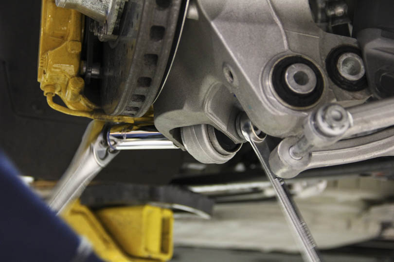
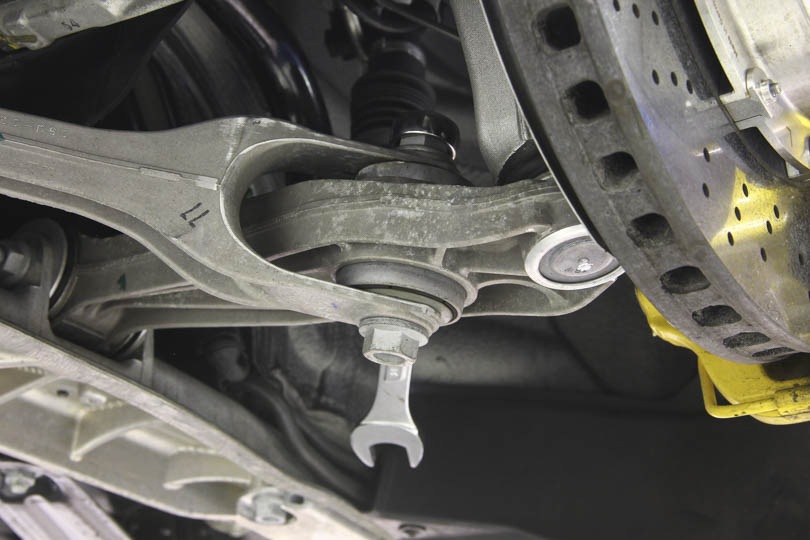
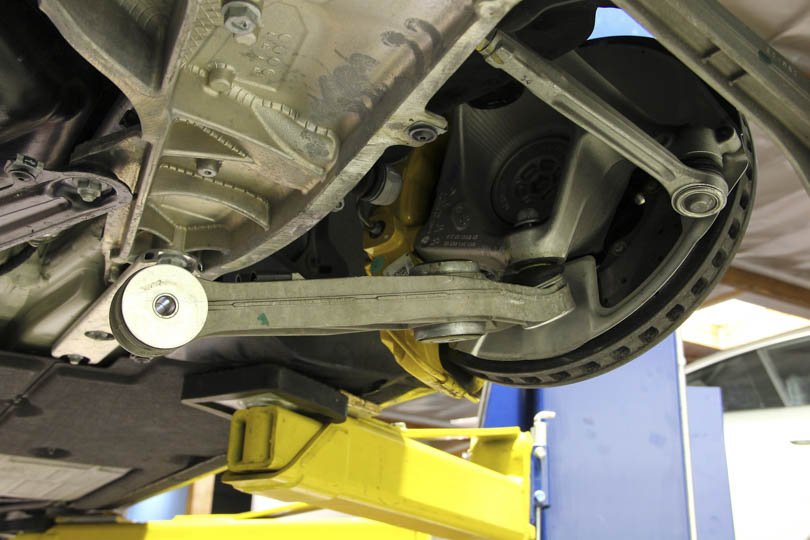
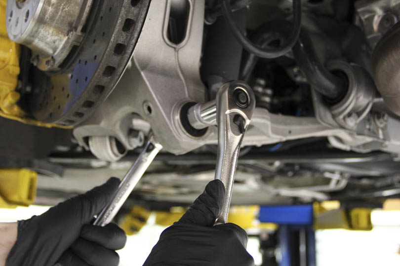
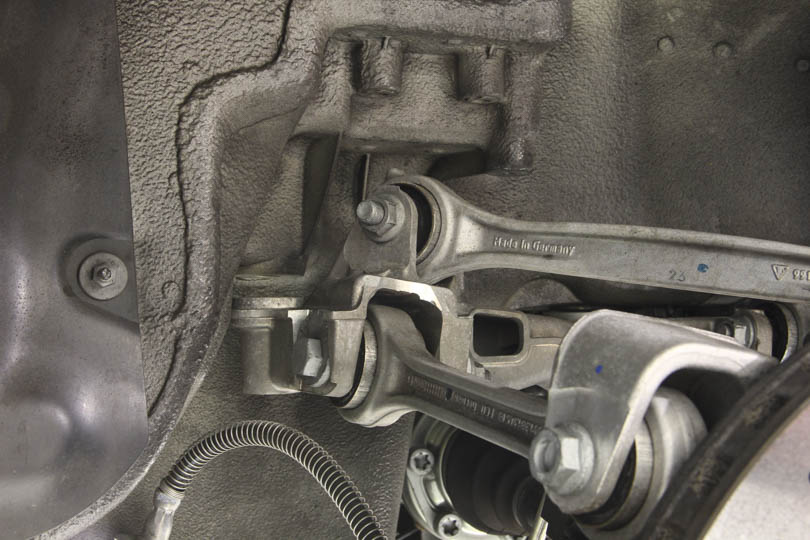
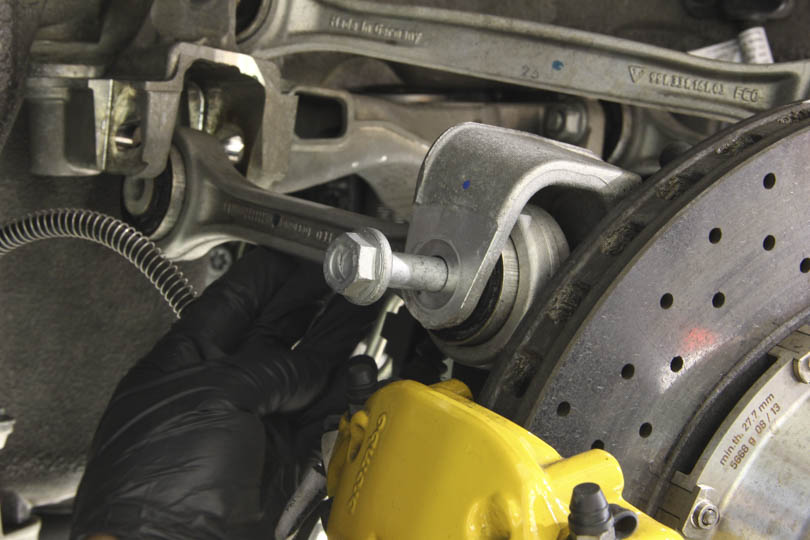
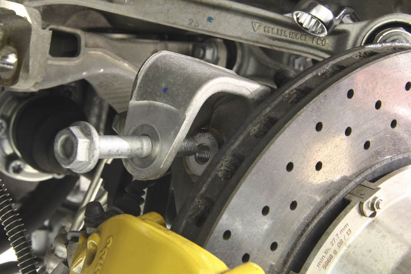
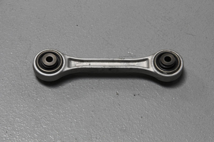
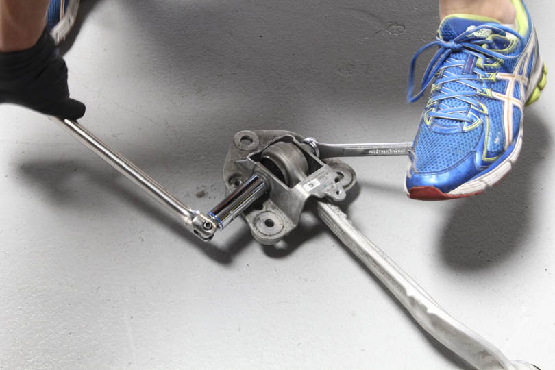
Disconnect the lower S-shaped control arm. This needs to be disconnected in order to pull the wheel carrier forward to get the shock out. Use 21mm wrench and an 18mm socket to loosen and pull the bolt out.
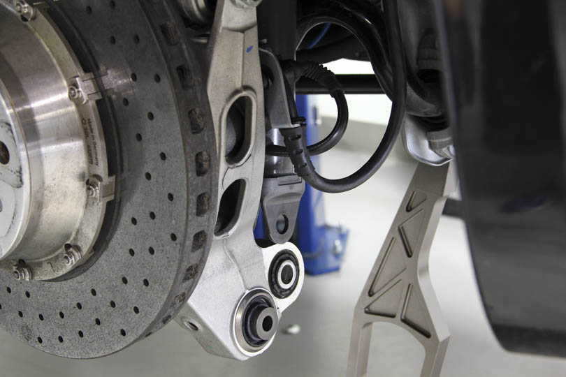
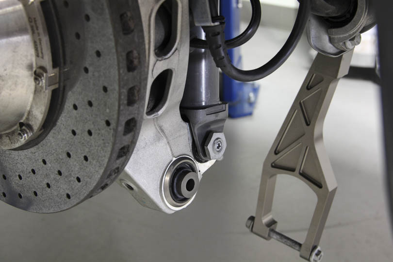
Disconnect the shock by removing the lower shock mount bolt. Torx T55 bit or socket is required. Hold the bolt with the Torx and loose the hex nut with an adjustable wrench then remove the bolt.
Pull the wheel carrier forward and slide the shock off the mount. Pulling the wheel carrier forward is required or otherwise the sway bar will be in the way of the shock.
The shock should come out now. The shock needs to be rotated in the wheel well and face towards the front of the car. There should be enough clearance to navigate the shock out.
Now that the shock is out of the way, we can move on to rebushing the control arms.
Upper Control Arm Removal
It’s best to re-bush each control arms in series. This way not all control arms are removed and the wheel carrier assembly is not left unsupported.
Let’s start with the upper control arms. If the lower control arms are disconnected, reconnect them for support. No need to torque them as we’ll be disconnecting them again.
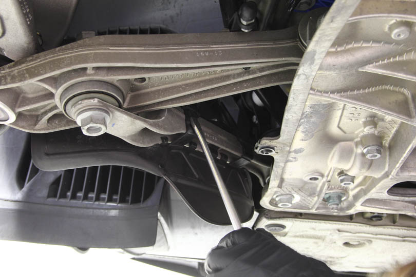
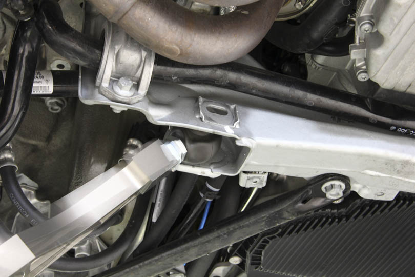
In order to remove the toe link, and the diagonal upper control arm, the subframe needs to be pivoted out. This is because the bolts that secure these control arms extract towards the chassis such that inadequate clearance is available unless you pivot out the subframe.
Fortunately, it’s a relatively quick and simple job.
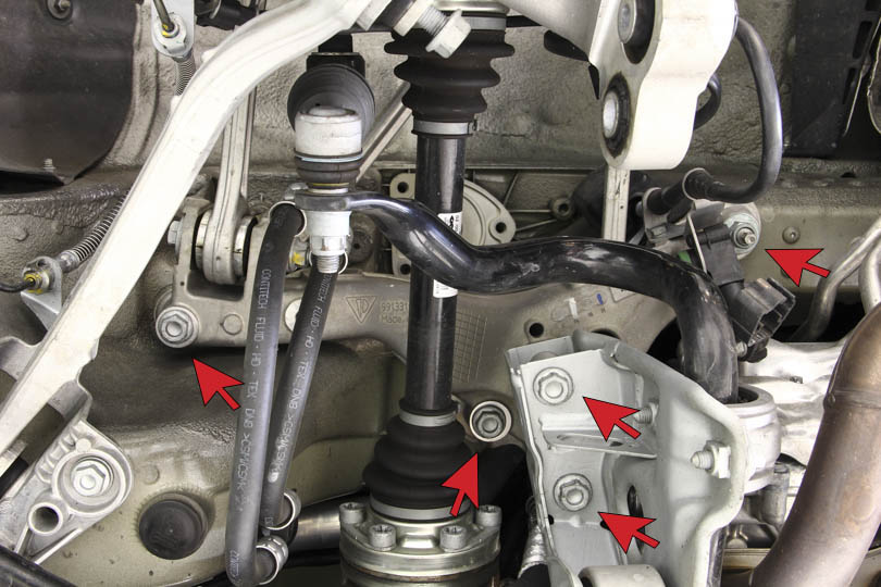
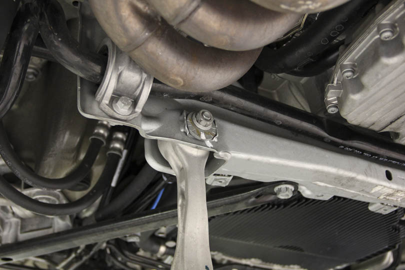
The subframe is held with 5 bolts as pointed above.
Also, just in case, remove the bracket that holds the evening sensor. It’s an M10 bolt.
Once all five bolts are removed, pull on the subframe so it drops about an inch. Then grab the toe link side and pivot the entire subframe outward using the inner bolt as a hinge.
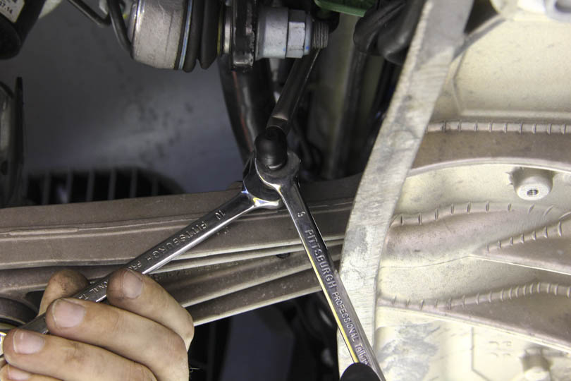
Now there will be enough access to insert an 18mm wrench and a socket. Remove the bolts from both arms.
Using an 18mm socket, unthread the outer bolt.
The bolt threads directly into the wheel carrier.
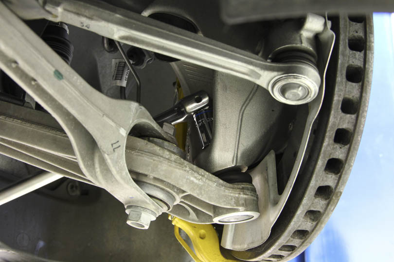
Remove the bolt from the upper diagonal control arm as well.
Both of the arms are out and ready for new bushings.
Rebushing Process
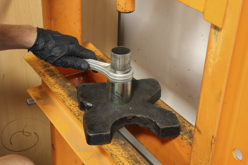
The bushings are roughly 44.5mm in diameter. Using a shop press, place the control arm on a section of pipe with inside diameter slightly larger than 45mm. When pressing the bushings out, we want the bushing to ‘fall’ into the section of pipe.
The top pipe has outside diameter of less than 44mm. It will be used to press the bushing out. Make sure that it is resting only on the metal sleeve and not on the rubber.
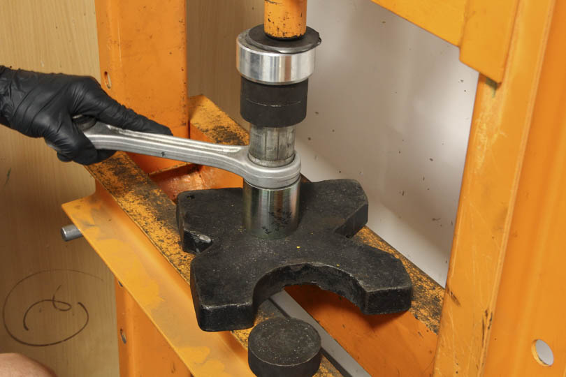
Apply pressure.
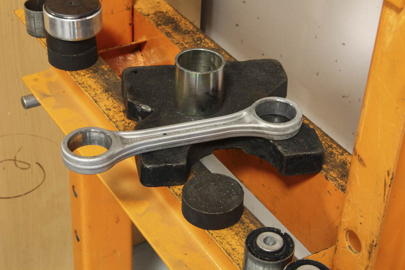
The bushings should press out without too much resistance. Repeat the same procedure on the other side.
Before pressing the spherical bearings in, clean the control arm bushing contact surface with brake cleaner to remove any grease or dirt. Apply the provided loctite 680 to the inside surface of the control arm and the bearing outer housing. You need to fully coat both parts on the contact surfaces, being sure to distribute the loctite over the entire contact surface.
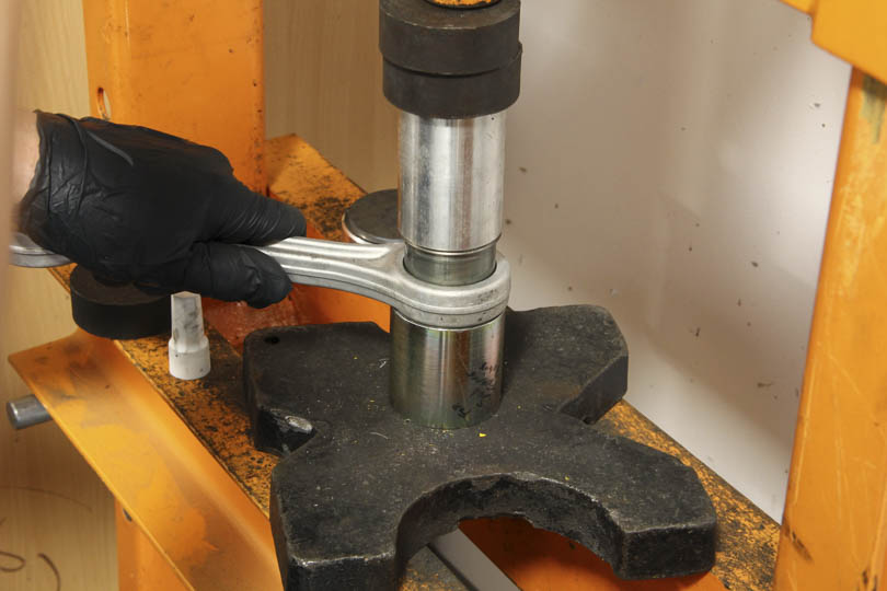
The same process but in reverse is used for pressing in the spherical bearings. Be sure you are pressing only on spherical bearing outer housing, and not the bearing center. Applying pressure to the bearing center can damage the bearing.
Make sure that the cylinder is only supported on the outer edge of the bearing and NOT on the spacer or the seal, as this can damage the bearing.
Pay careful attention to ensure the bearing is pressing in straight. If the bearing begins to get cocked to one side, you need to straighten it before proceeding or damage to the arm or bearing may result.
The bearings should press in with little hesitation or resistance. After pressing them in, insert a long bolt or screwdriver through the hole to act as a lever and pivot the bearings. You will feel some resistance but should be able to pivot the bearings with hand pressure using the added leverage of a typical screwdriver.
Repeat the same procedure for the diagonal upper control arm.
Upper Control Arm Installation
Reinstall the toe link.
We’ve decided to insert the bolts backwards. We’re not sure why Porsche decided to insert the bolts as they did, inserting them backwards resolves the clearance issues so the next time the arms need to be removed, the subframe will not need to be lowered.
Also reinstall the diagonal control arm and pivot the subframe back in place and bolt it back on.
Please note that the subframe fit is loose. It has about 3mm slop around the bolts and studs securing it. Be careful aligning the subframe and torquing to correct spec.
Now move on to the other upper outer control arm. This arm is fairly simple to remove, use 18mm socket as with the rest of the arms and repeat the same re-bushing process as described above.
Once the upper control arms are re-bushed and reinstalled. The lower control arms can be removed.
Reconnect the leveling sensor.
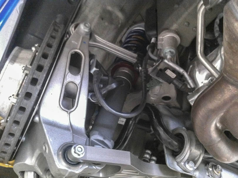
Lower Control Arm Replacement
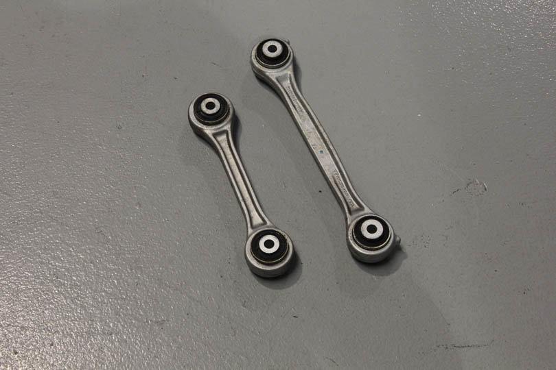
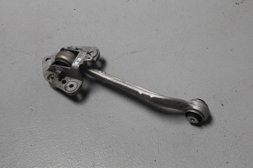
Now remove the S-shaped arm.
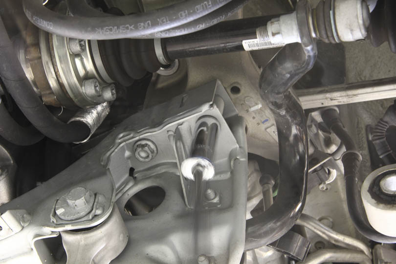
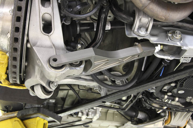
To remove the arm the entire inner support bracket needs to be removed with it as there is no clearance to fit a wrench. The black diagonal brace bar needs to be removed as well.
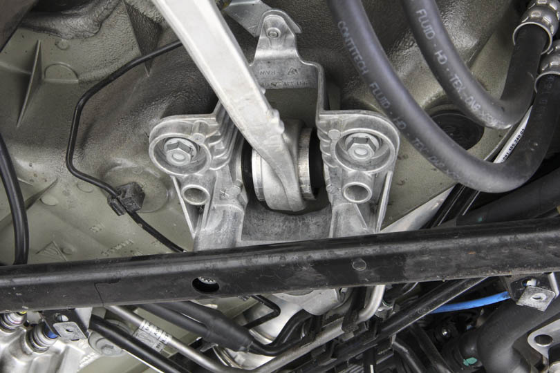
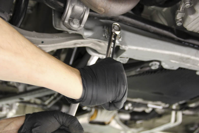
The diagonal brace is held with three bolts, an 18mm on each side and a torx 12 point m12 in the middle.
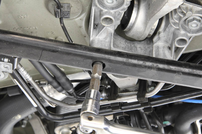
Remove all bolts and set the diagonal brace aside.
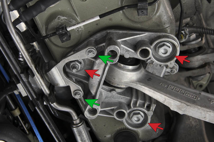
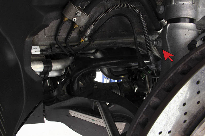
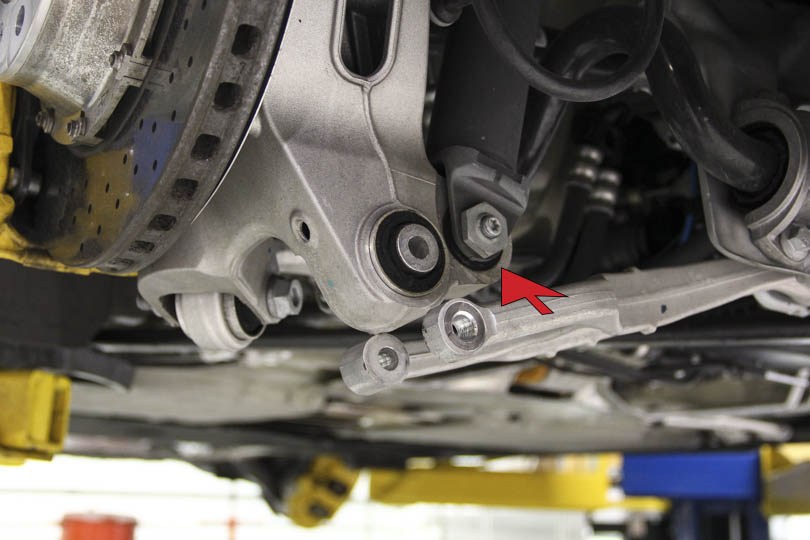
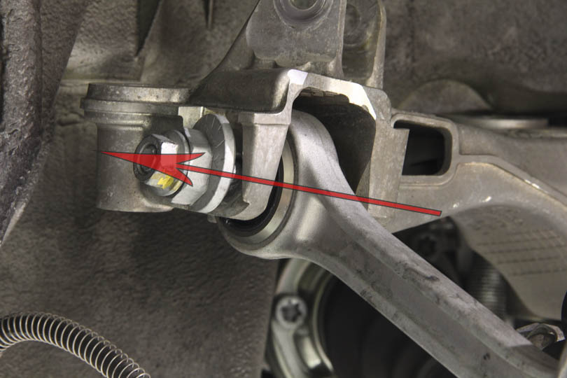
The bracket is held with three 16mm bolts. The brake line support also needs to be disconnected. It’s held with two star head bolts (green arrows).
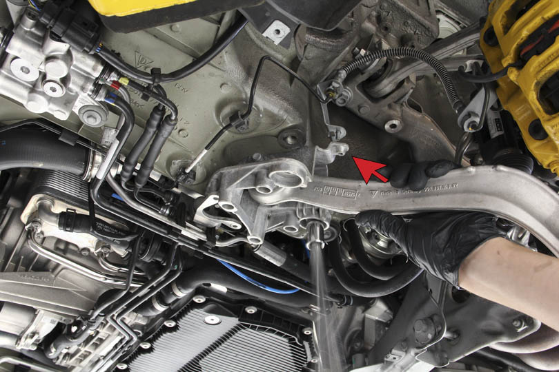
There’s also an upper brake line support bracket that needs to be disconnected (red arrow) with a 10mm socket.
The entire assembly arm will come out. Now the bolts can be accessed.
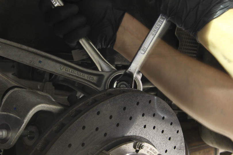
Detach the control arm from mounting bracket using a 21mm socket and 18mm wrench. This bolt is pretty tight so it will take some force to loosen it up.
Once the arm is extracted, repeat the same re-bushing process as described above.
Attach the control arm back to the housing bracket using a 21mm wrench and 18mm socket, and reinstall bracket and control arm in reverse order.
Reinstall crossmember support.
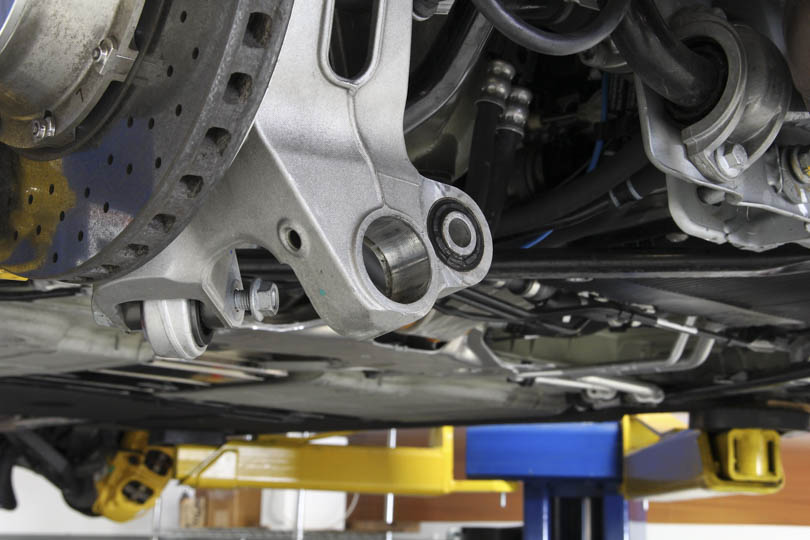
Wheel Carrier Bushing Installation
Pressing out the wheel carrier bushings.
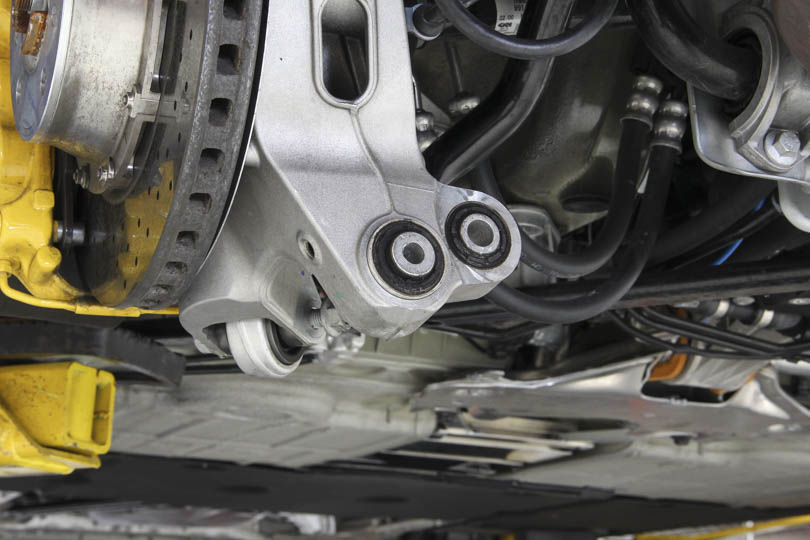
Normally the entire wheel carrier assembly would have to be removed in order to press out these bushings. However, we’ve devised a method which allows the bushings to be pressed out in place. Saving lots of time. We will soon offer for sale a tool that make it easy to remove and insert the bushing in situ. But you can also fabricate your own tool as shown here.
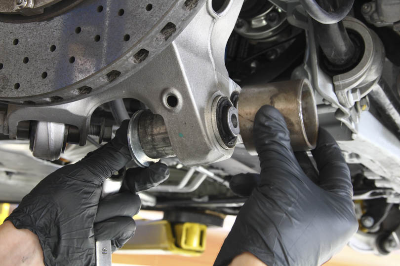
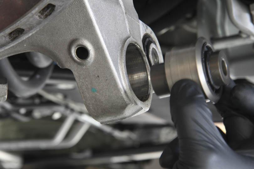
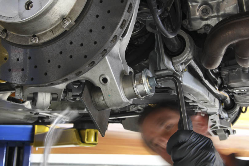
Press out wheel carrier bushing by using two cylinders; one with slightly smaller outside diameter than the bushing and the other slightly larger. Take two large washers or a metal plate with hole drilled, and sandwich the bushing. Insert the bolt through and thread it with a nut. Using two wrenches, crank on the bolt so that the bushing presses out into the larger OD cylinder.
The bushing should press out with ease.
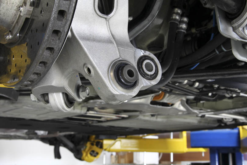
The new bearing can be inserted in reverse order.
Clean the wheel carrier bore with brake clean to remove any grease. Then apply a coating of the loctite 680 to both surfaces and fully distribute over the contact area.
Press the bearing in with an installation tool that rests on the flange part of the bushing housing, but not on the rubber seal or the spacer, as this can damage the bearing. Be careful to align the bolt so the bushing presses in straight.
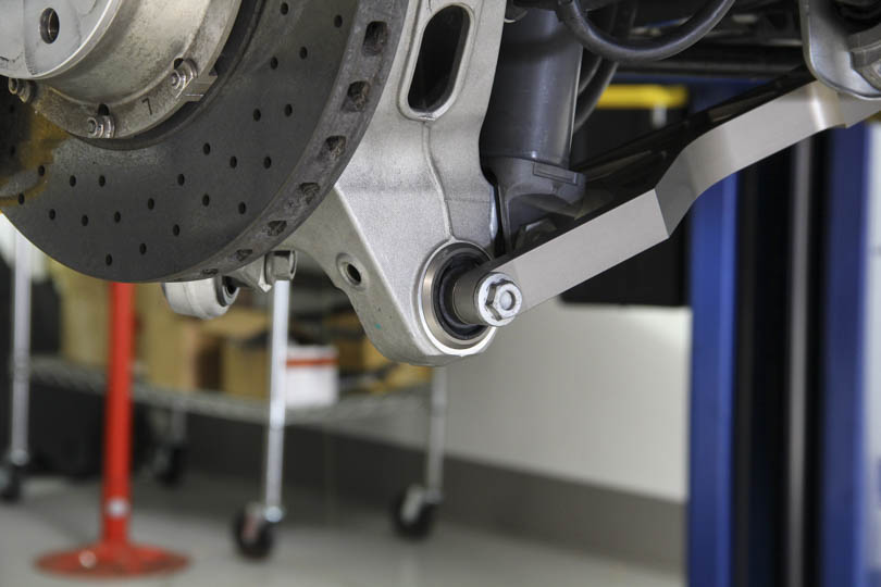
Lower Wishbone Replacement
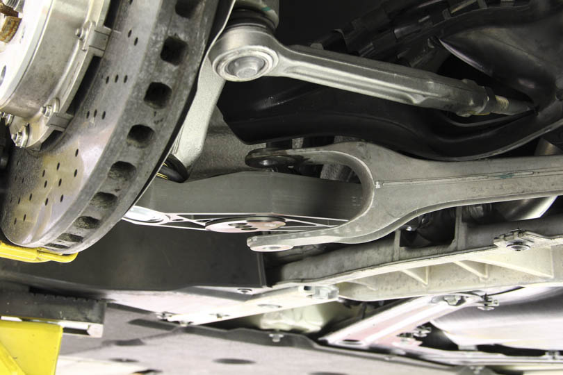
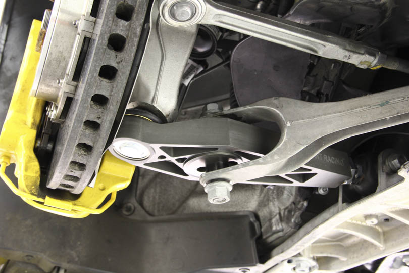
Once the bushing is pressed in, lower control arms can be reinstalled. On this car, we’re replacing the OEM arm with our adjustable control arm.
Push the heim joint side in first. It may be a tight fit but don’t be afraid to tap it into place using a rubber mallet.
Reinstall the eccentric bolt but not the outer bolt as the rear shock has not been installed yet.
Shock Coilover Conversion
Now we can move on to the rear shock sleeve kit.
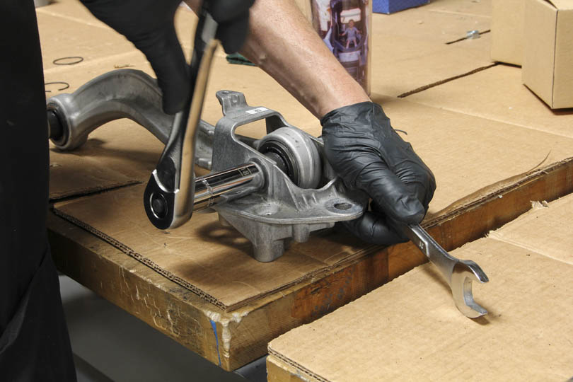
Remove the top shock mount by using a 19mm deep inset box wrench and a 9mm open end wrench to hold the rod in place.
Then remove the spring, boot and the lower spring perch and the rubber seal.
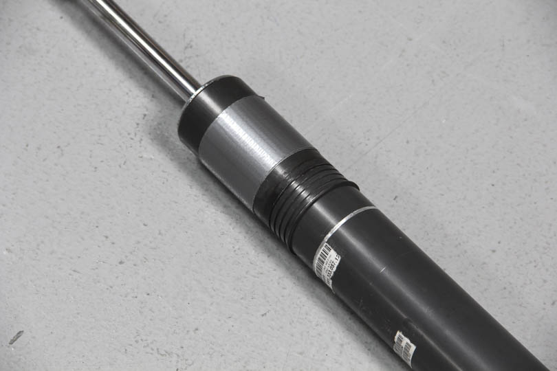
There are five grooves machined into the shock body. Move the snap ring to lowest position. Also apply two layers of duct tape or masking tape for tight sleeve fit.
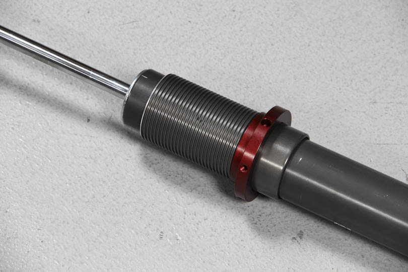
Pull sleeve over and thread on the lower perch.
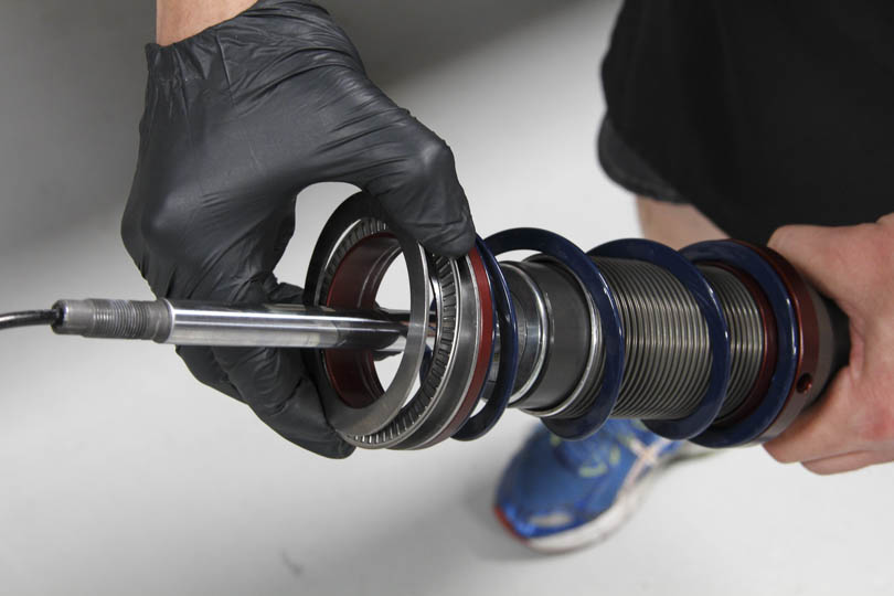
Insert the helper spring on top of the lower perch following with the spring divider. On top of the spring divider place the seat bearing sandwiched between two washers.

Insert the main spring and the upper shock mount and bump stop.
Just like before, reinstall the top shock mount using a 19mm deep inset box wrench and a 9mm open end wrench to hold the rod in place.
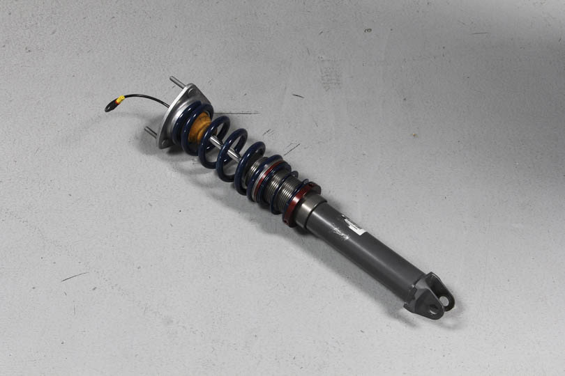
Rear coilover ready for installation.
Rear Shock Installation
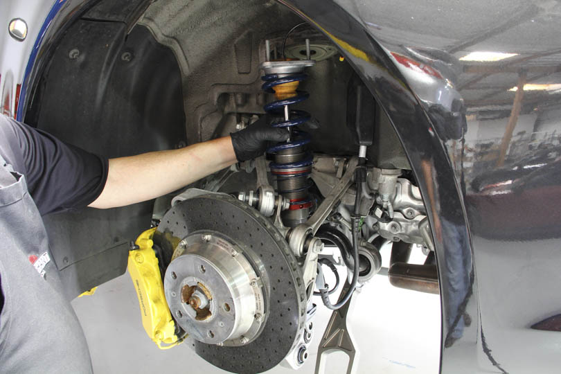
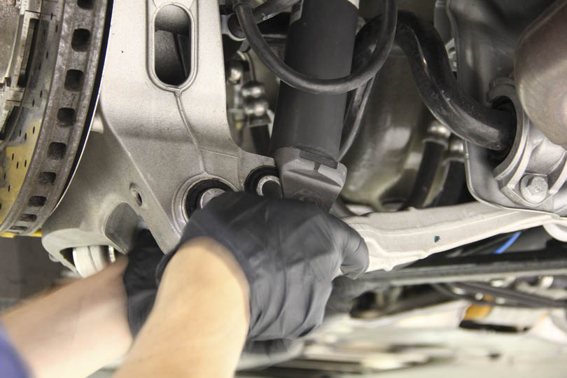
With the rear assembly at full droop, navigate the rear shock onto the lower mounting bushing.
Bolt down and torque.
Re-attach the lower control arm and torque.
Raise the assembly so the upper shock mount bolts pass through the mounting holes, and torque them down from the inside of the car. Reattach the PASM cables.
Torque all bolts to specifications.
The job is almost done. Now the suspension will need to be realigned and corner balanced.